
The Magpower Avengers 125 is based on a compact V-Twin engine whose wiring harness withstands both the vibrations of the twin-cylinder and varying weather conditions. Electrical failures on this model often manifest intermittently, complicating their identification. The diagnosis becomes more effective when it follows a circuit segmentation logic rather than random part replacement.
Battery Voltage and Charging Circuit on the Magpower Avengers 125
The first reflex when facing an electrical failure is to measure the battery voltage. However, this single measurement is not enough to make a reliable diagnosis. Three distinct readings with a multimeter allow for precise problem identification.
With the engine off, the voltage at the battery terminals indicates a resting charge state. During startup, the voltage drop reveals the battery’s ability to provide sufficient cranking current. With the engine running at a stabilized speed, it is the regulation of the stator and the regulator-rectifier that is put to the test. Differentiating between a weak battery and a regulation failure requires these three measurements, not just one.
A detailed article addresses the reliability issues of the Magpower Avengers 125 from the perspective of replacing charging components. The approach remains complementary: before changing anything, segmented voltage readings prevent blaming the battery when the stator or regulator is at fault.
Connectors and Grounds: The Phantom Failures of the Wiring Harness
On the Magpower Avengers 125, connectors and ground points age poorly. The V-Twin generates vibrations that gradually loosen the pins, while moisture accelerates contact corrosion. The result: intermittent electrical cuts that are impossible to reproduce when stationary.
Identifying a Loose Connection in the Wiring Harness
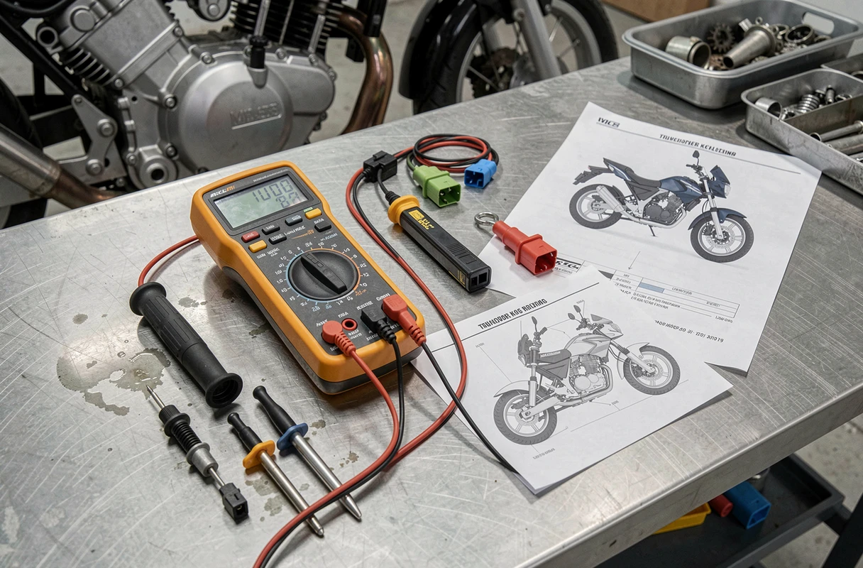
A classic static check (multimeter at the terminals, engine off, motorcycle on a stand) often misses these failures. Recent motorcycle diagnostic guides recommend reproducing the actual failure conditions: operating temperature reached, accessories on, motorcycle vibrating.
The method involves gently shaking the wiring harness, section by section, while a test light or multimeter monitors the continuity of the circuit. As soon as the signal drops, the faulty section is identified.
Priority Checkpoints
- Connectors located near the engine, exposed to heat and vibrations from the V-Twin, often show blackened or melted plastic, a sign of abnormal heating due to contact resistance
- Ground points fixed to the frame or engine loosen over time, creating a parasitic resistance that disrupts the entire circuit
- The fuse holder deserves a visual and tactile inspection: a fuse that appears intact may have a corroded leg or a socket enlarged by vibrations
Cleaning the pins with contact spray, tightening the ground terminals to specification, and replacing questionable connectors with waterproof fittings eliminates a large portion of so-called phantom failures.
Segmented Diagnosis: Isolating the Failure Without Random Replacement
Replacing the starter relay, then the coil, then the CDI in hopes of hitting the right part remains a costly and random approach. Testing the circuit in segments reduces diagnostic time and the number of parts changed unnecessarily.
Circuit Segmentation Method
The principle relies on breaking down the circuit into four functions: power, control, ground, and load (the final component). Each segment is tested independently.
- Check that power reaches the suspected component by measuring the voltage upstream of the relevant connector
- Control the command: does the switching signal (relay, kickstand switch, kill switch on the handlebars) reach the component when the corresponding command is activated?
- Test the ground: one probe of the multimeter on the negative terminal of the battery, the other on the ground wire of the component, to measure the resistance of the current return
- Evaluate the component itself (starter, ignition coil, fuel pump) only after validating the first three points
This approach highlights defects that blind replacement does not resolve. A new starter will not solve anything if the engine ground is interrupted by a corroded screw.

Kickstand Sensor and Starter Relay: Two Recurring Suspects
Among the specific failures of the Magpower Avengers 125, the side stand switch frequently appears in field reports. This sensor prevents starting when the stand is deployed, but its operation degrades with dirt or corrosion. The motorcycle then refuses to start for no apparent reason, with the stand up.
The test is simple: disconnect the sensor connector and bridge the two wires. If the starter turns, the sensor is at fault. The replacement is inexpensive, but the diagnosis prevents mistakenly changing a relay or starter.
The starter relay is checked by listening for the characteristic click when pressing the start button. Absence of a click with a charged battery: the relay or its control is faulty. A relay that clicks without engaging the starter points to an engine ground or starter issue.
Limitations of Amateur Diagnosis on the Magpower Avengers 125
Failures related to the electronic control unit (ECU, Delphi injection) remain difficult to diagnose without an OBD reader suitable for two-wheelers. Field reports vary on the reliability of these units depending on the production years. A multimeter and a test light cover the majority of wiring, ground, and electromechanical component failures, but not software defects or pressure and temperature sensors integrated into the injection system.
Before considering a shop visit, the segmented diagnosis described above allows for the elimination of simple causes. If the failure persists after checking power, grounds, and controls, the problem likely lies in the electronic management, and using a fault code reader becomes the logical next step.